According to data from the U.S. Fire Administration's National Fire Incident Reporting System (2000-2004) and a survey by the National Fire Protection Association (NFPA), NFPA estimated that 32 percent of all home structure fires involved cooking equipment.
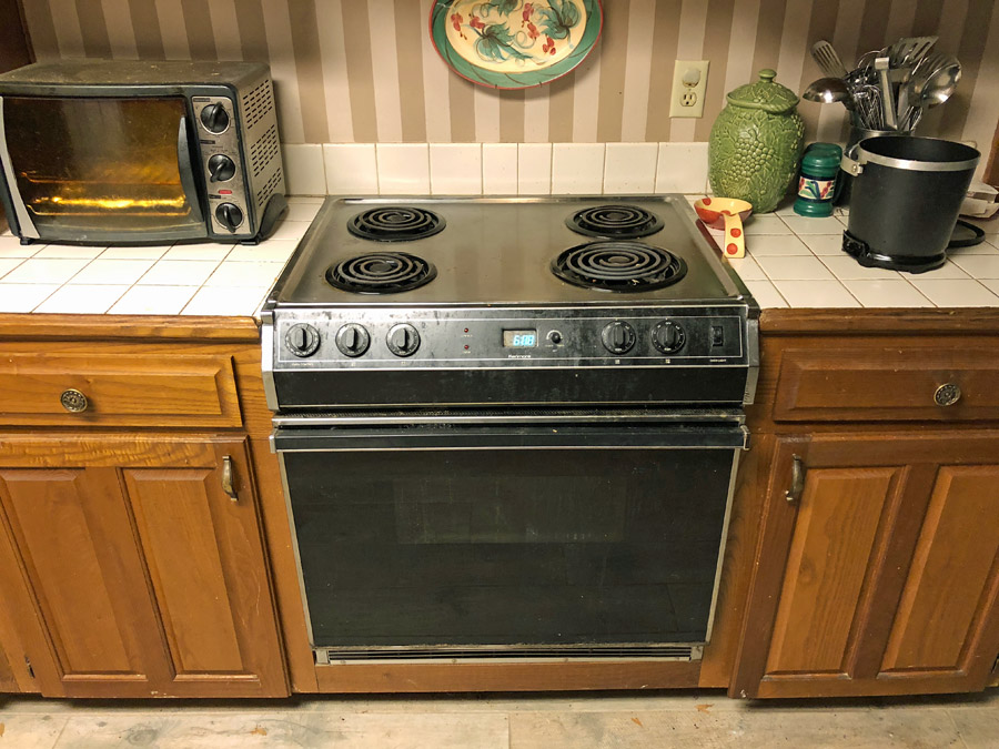
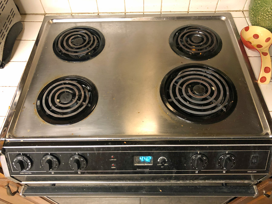
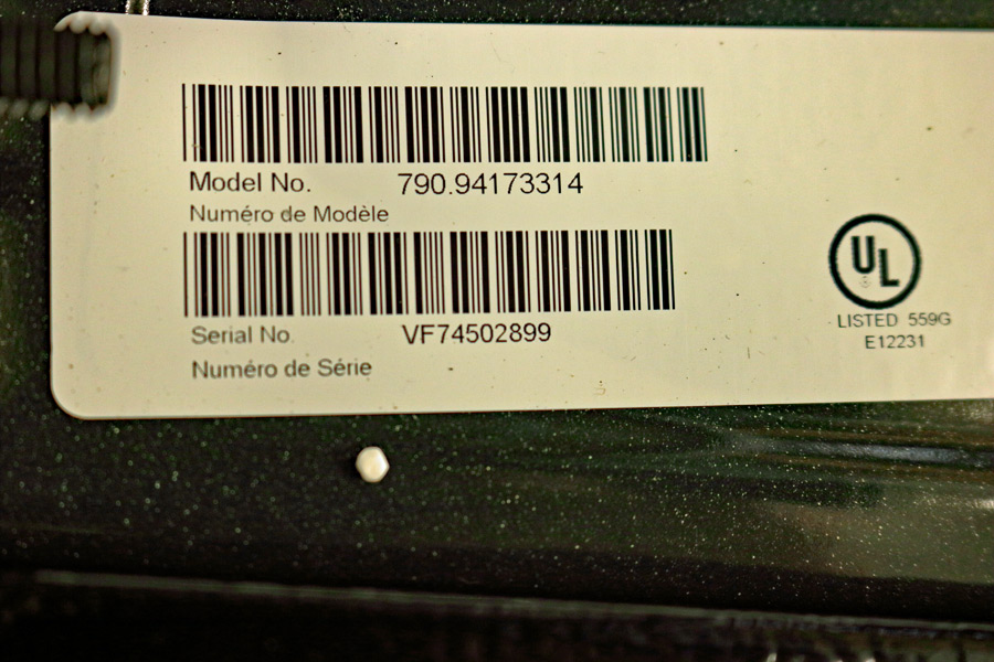
My Kenmore range was manufactured in January of 1990 by Roper. It is built into the counter, which makes it difficult to work on. It has one 8-inch surface heating element (2,100 Watts) and three 6-inch heating elments (1,250 Watts).
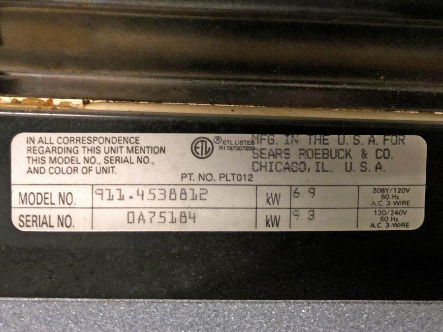
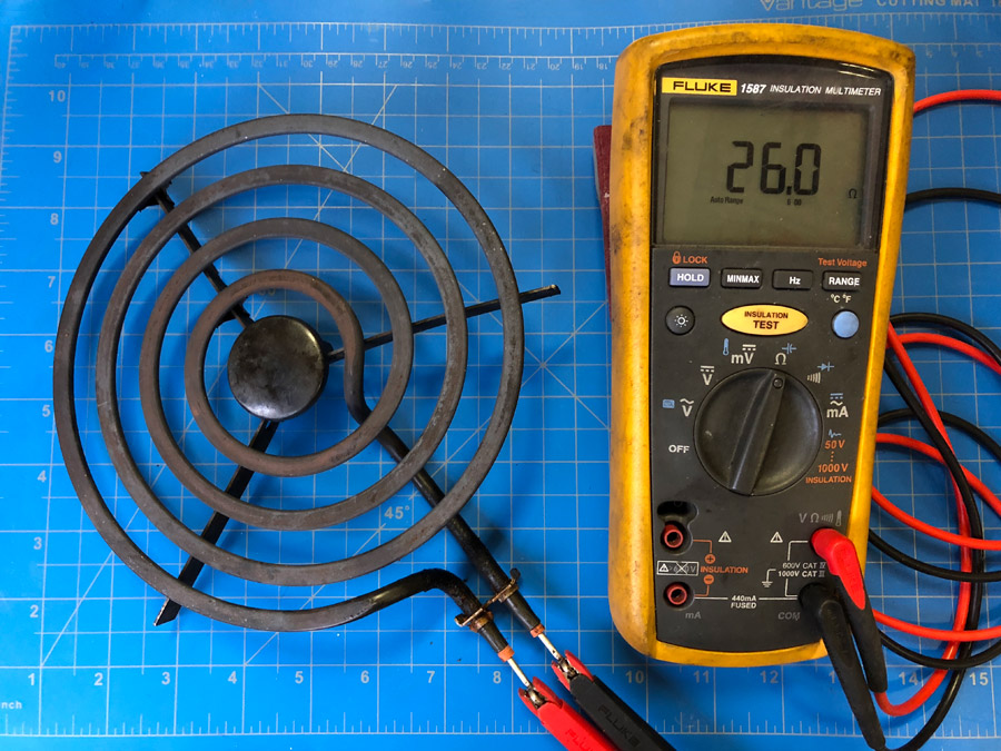
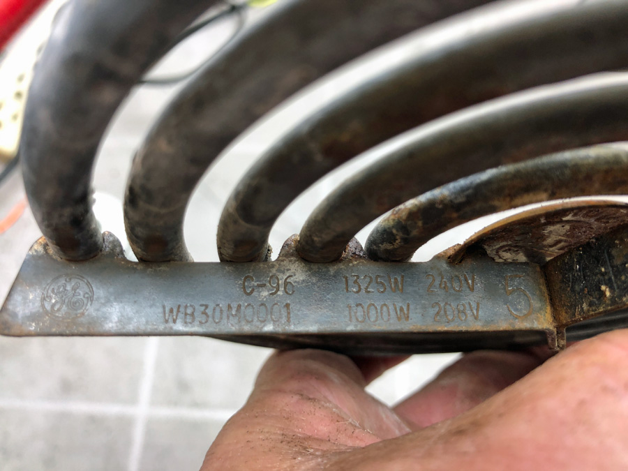
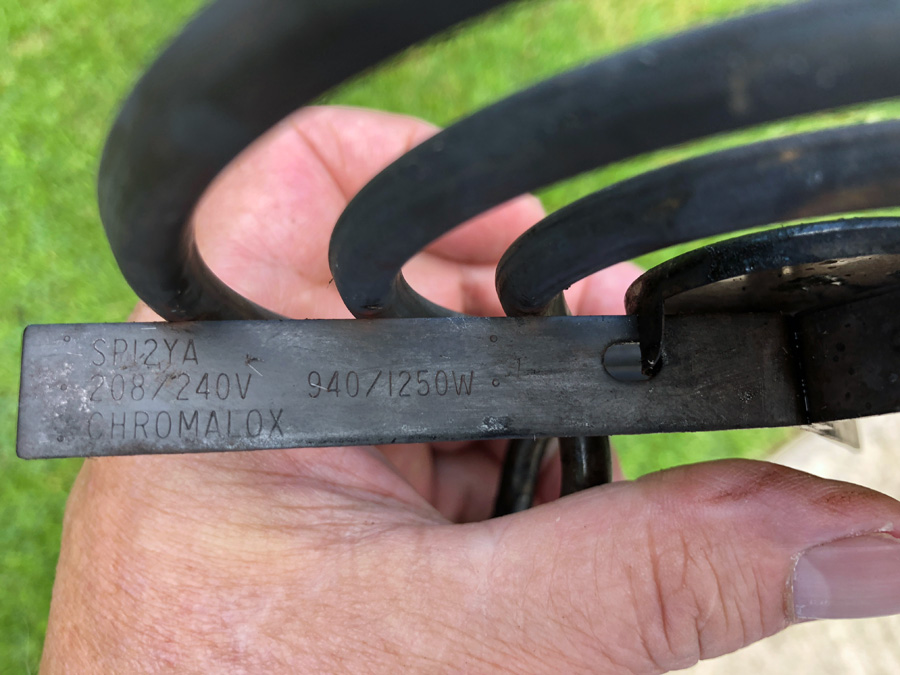
Part Numbers and Wattages are often stamped into the rails of range surface burners. To see the numbers, you usually have to use some type of brush. A Google search of the part number will usually reveal the manufacturer.
Surface burner switches control heat from low to high and everywhere in between; hence, they are often referred to as "infinite" switches. The position of the switch can usually be determined from the position of the notch or detent in the plastic cam. The plastic housing and cam are made of a thermoplastic that does not melt. The switch stems and die casting on the back of the steel (2600°F) faceplate are made of plot metal, which melts at approximately 800°F.
For Maximum Resolution, Click on the Body of the Picture.
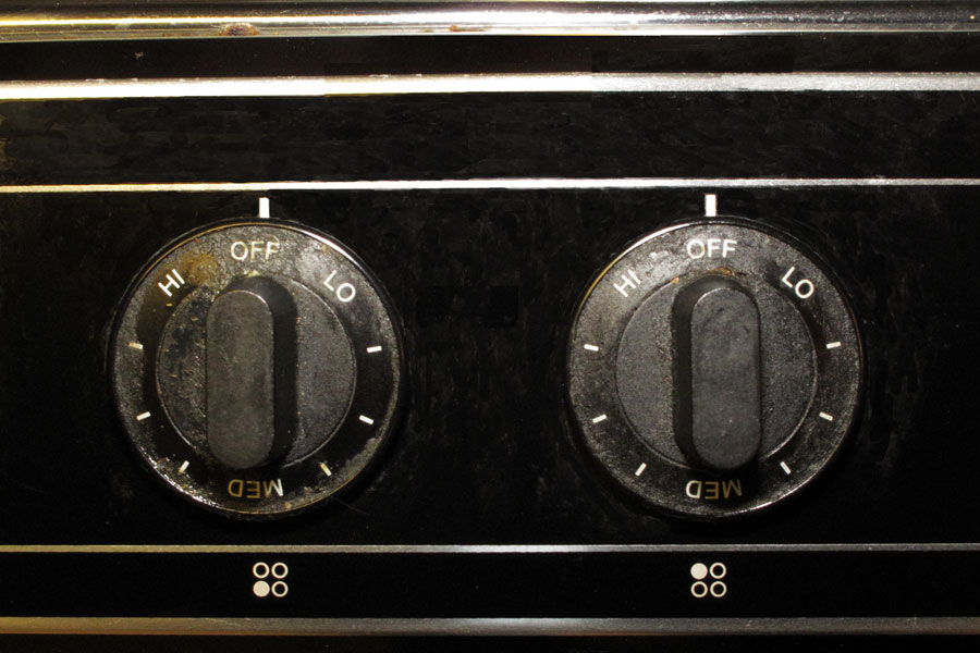
Infinite Switch Knobs turn Counter Clockwise.
The Outer Knobs control the Front Burners.
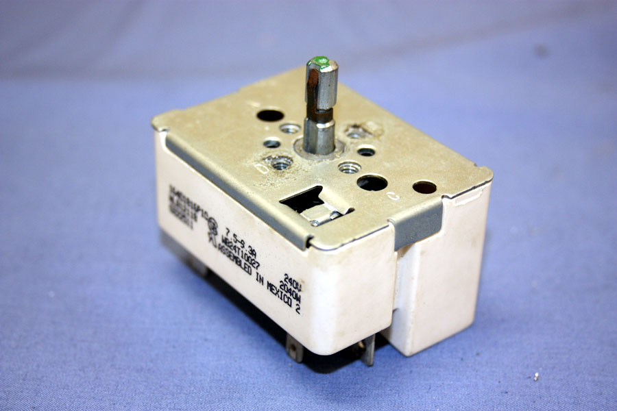
Typical Range Infinite Heat Switch.
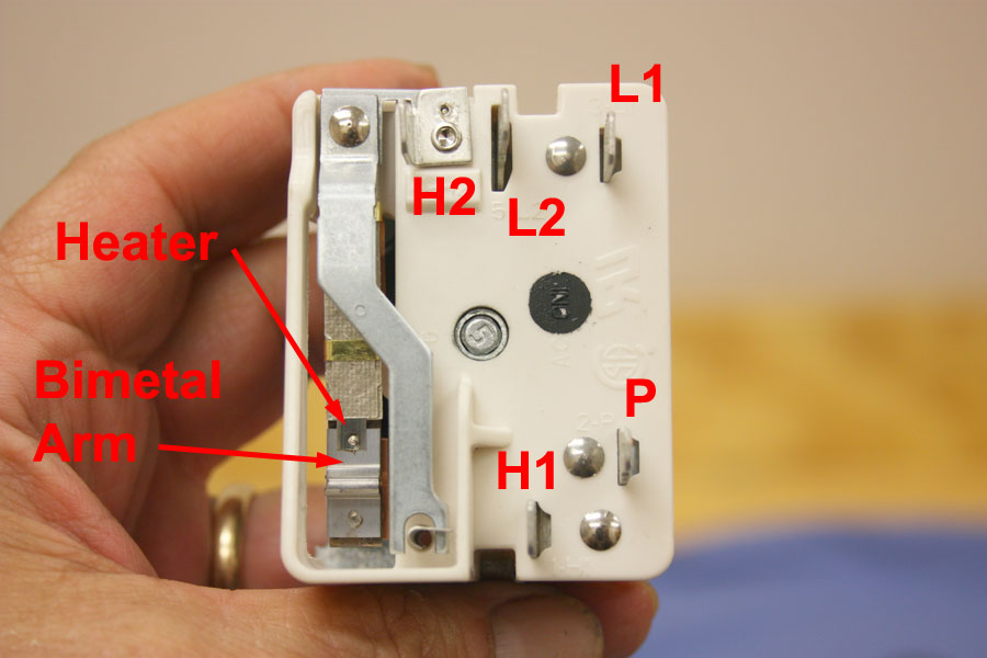
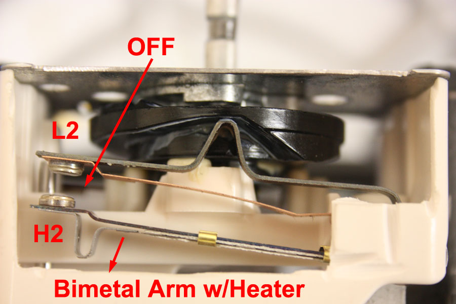
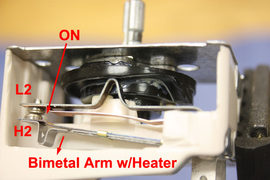
Infinite Switch - Bimetal Arm and Terminals.
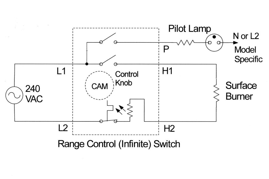
Infintie Switch Schematic.
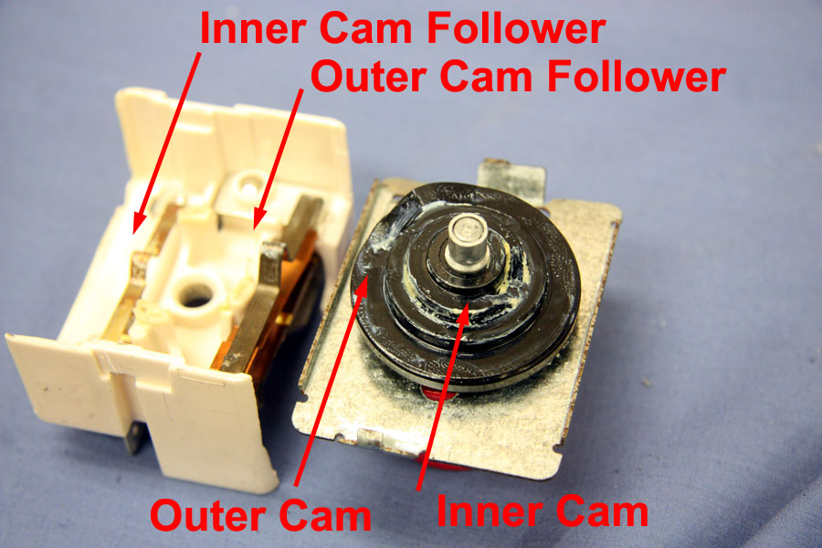
Inner and Outer Cam Followers.
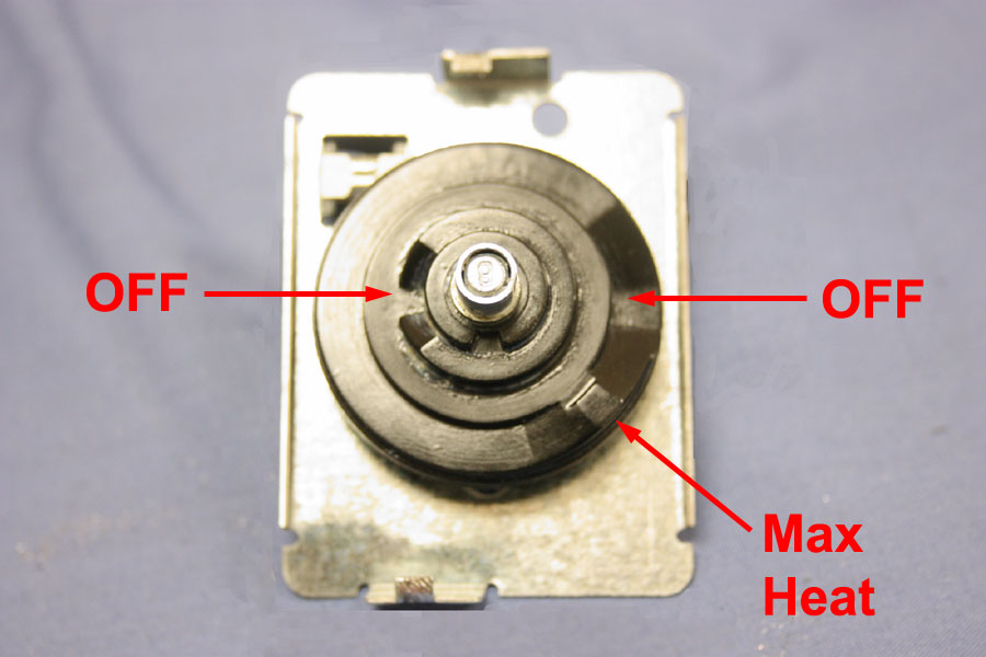
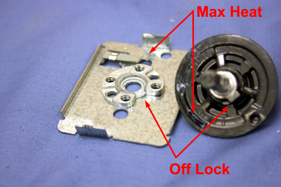
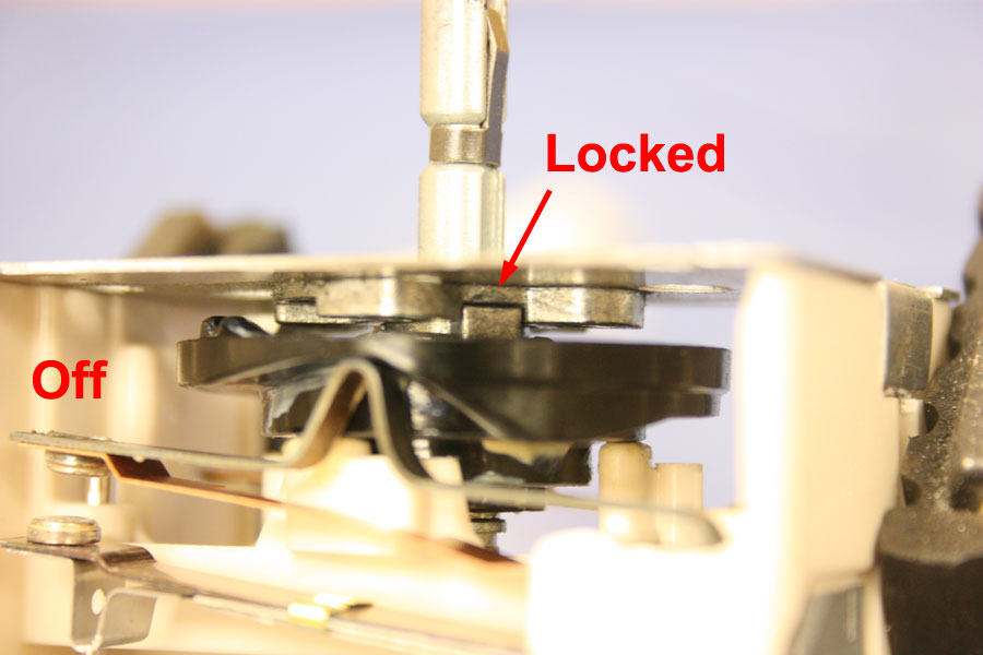
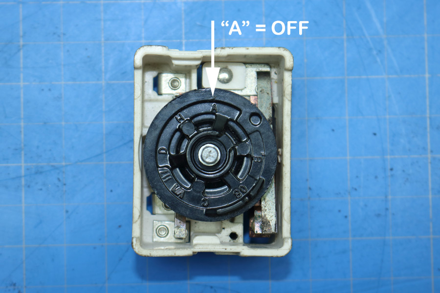
Indentions in Inner and Outer Cams Depicting the "OFF" Position.
When in the "OFF" Position, the Indention in the Inner Cam
is aligned with the Metallic Notch of the Inner Cam Follower.
When in the "OFF" Position, the Indention in the Outer Cam
is aligned with the Metallic Notch of the Outer Cam Follower.
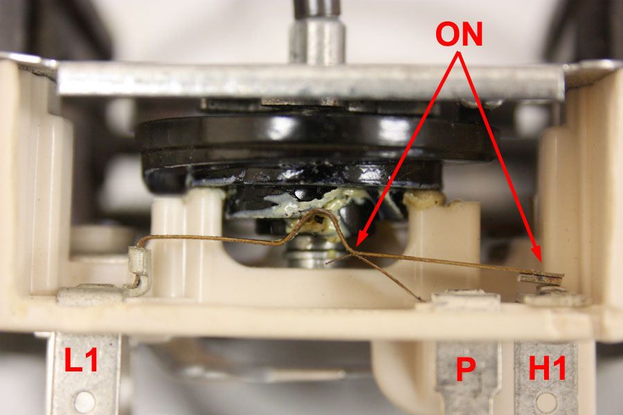
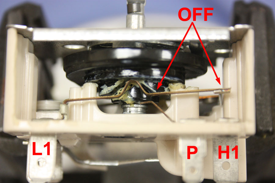
When in the "ON" Position, the Inner Cam presses down on the Arm
of Inner Cam Follower,
which closes the Pilot and Heater "1" Contacts.
When "ON", the Outer Cam presses down the Arm of the Outer Cam
Follower closing the Contacts.
The Bimetal Arm opens the Contacts.
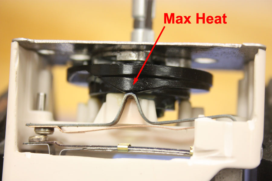
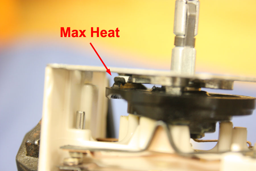
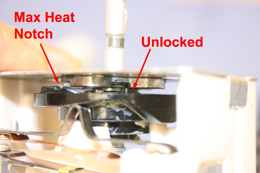
In the Max Heat Position, a High Spot on the Outer Cam insures
that Heater "2" Contacts are Always Closed.
There is also a Seperate Cam Follower for the Max Heat Position
and an Indention on the other Side of the Plastic Cam.
When the Switch is "OFF", the Notch on the Metallic Stem fits
into the Indention on the Back of the Metallic Face Plate.
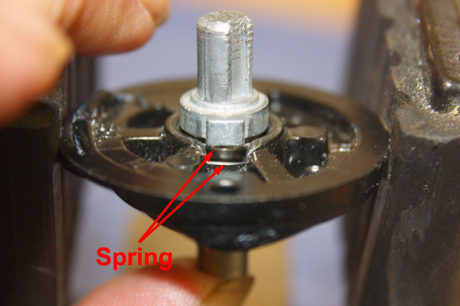
To Move the Switch from the "OFF" Position,
the Metallic Stem must be pushed into the Plastic Cam.
The Knob has to be pressed "In" to be moved from the "OFF" Position.
Position of Metallic Notch on the Stem,
when the Switch is in the "ON" Position.
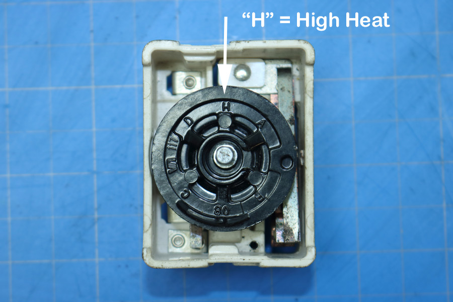
On the top of the plastic cam there are raised letters and numbers. These can be used to determine the position of the cam. When the letter "A" is at the 12 o'clock position with respect to the switch body, the switch is in the "OFF" position. When the the letter "H" is in at the 12' o'clock position to the switch is in the max heat position. There is only 1/8 of a turn between the "OFF" position and the max heat position.
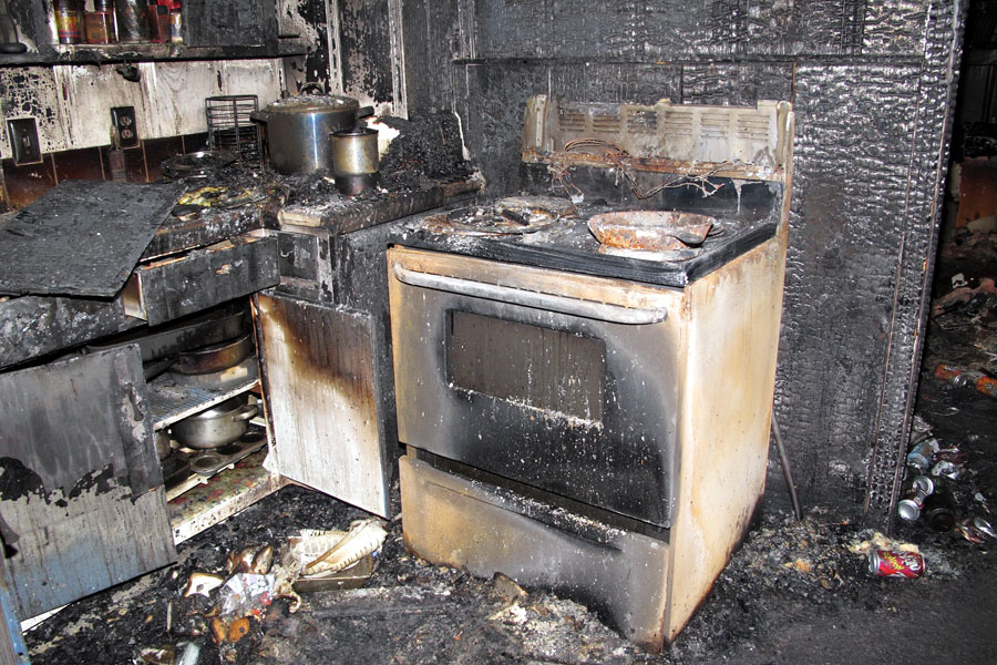
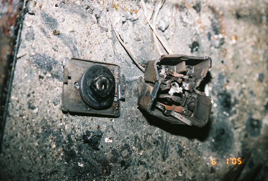
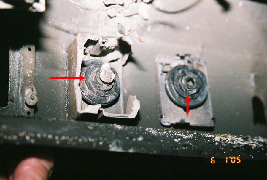
A new Tappan range was purchased the weekend before Thanksgiving 2009. A kitchen fire occurs three days after the range was installed. The homeowner's daughter (age 15) and son (age 10) were out of school the week of Thanksgiving. Both parents were at work. All of the surface burners except the right rear had covers over them. A cast iron skillet was found on the range. When I examined the scene, all of the debris had been removed from the top of the range, and all that was visible of the infinite switches were the metallic cam follower arms, which were still attached to the wires. The two right infinite switches were found inside the back of the range. The green arrow points to the inner detent of the switch that was "OFF", the red arrow points to the inner detent of the switch that was "ON". If the green arrow is at 12 o'clock (OFF), the red arrow is at 8 o'clock (between Medium and High). The left two infinite switches were found on the floor. One of the two plastic cams was found, but it was not attached to the switch faceplate. This fire was investigated by the local fire department. It is presumed that they discarded the left two switches when they cleared the debris off of the top of the range. None of the plastic switch housings were found.
For Maximum Resolution, Click on the Body of the Picture.
New Tappan Electric Range (F09-67).
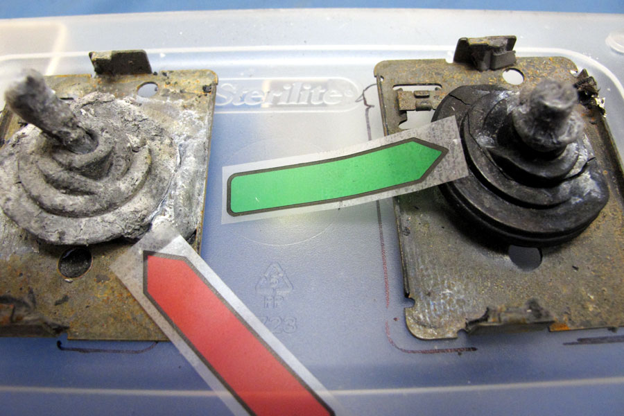
Position of Right Infinite Switches (F09-67).
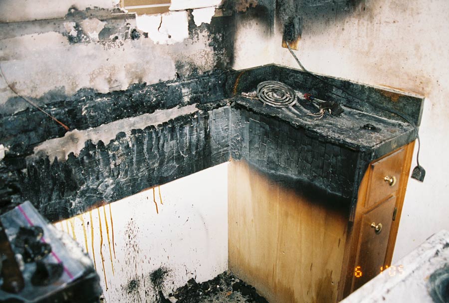
A fire occurred at this home two months after a new Black & Decker coffeemaker was purchased. Guest stayed overnignt. They got up the following morning and used the griddle to cook bacon and eggs. Both the knob stem and the cam detent showed that the right front burner under the griddle was "ON".
For Maximum Resolution, Click on the Body of the Picture.
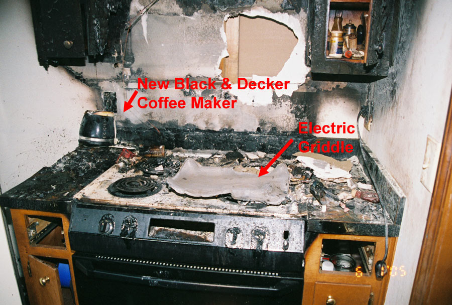
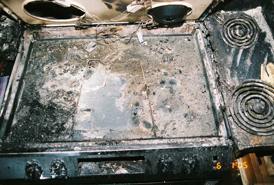
Electric Range (F05-15).
Vent Hood with Shaded Pole Fan Motor (F05-15).
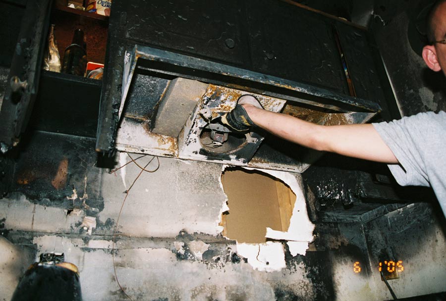
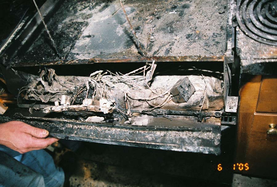
Underside of Range Cooktop (F05-15).
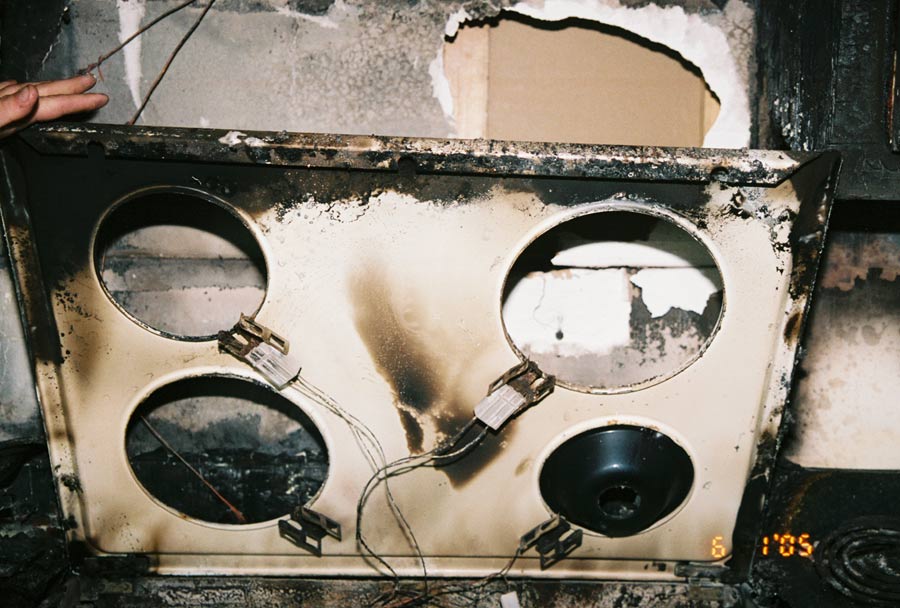
Bottom of Range Cooktop (F05-15).
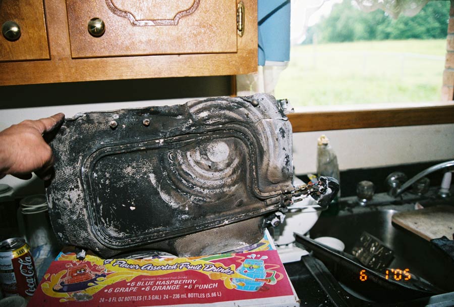
Bottom of Electric Griddle (F05-15).
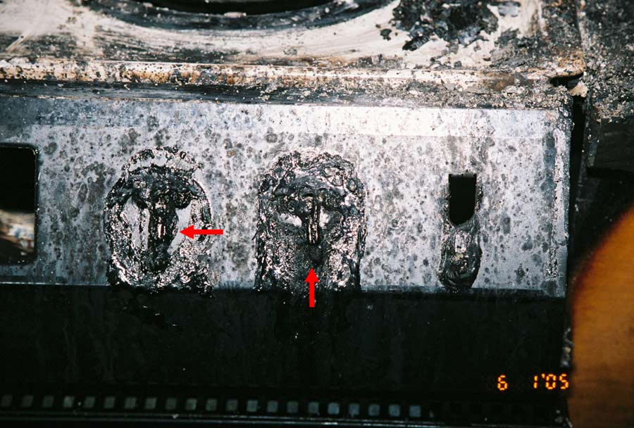
The Arrows Point to the Position of the Slot in the Stems (F05-15).
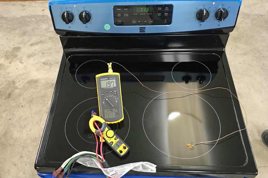
Range Control Panel (F05-15).
Surface Burner Control Switch - Infinite Switch (F05-15).
The Arrows Depict the Position of the Cam Indention. (F05-15).
Cabinet Space for Range (F05-15).
Some fire investigators incorrectly believe that if copper beading is present on the pilot light wiring then the range had to be "ON". Although one end of the pilot light circuit is energized through "L1" of the infinite switch, the other end of the pilot light circuit can be connected to either the "neutral" or "L2". As depicted in the schematic of the Tappan Range TEF242BW , one end of the pilot light circuit is always energized by "L2" regardless of the position of the infinite switch; hence, any short circuit on this wire can cause copper beading. Furthermore, even in the case were the pilot light circuit is referenced to the neutral, it is possible for an energized conductor to come in contact with the pilot light circuit and cause copper beading. On all of the cooktops (without ovens) that I have examined, one end of the pilot light circuit has been directly connected to "L2".
For Maximum Resolution, Click on the Body of the Picture.
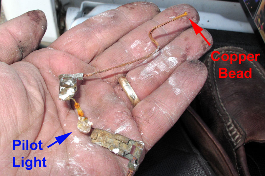
Copper Bead on Pilot Light Wiring (F09-071).
Frigidiare Range, Model FEF352FU, Coil Surface Burners, 120 VAC Pilot Lights
Tappan Range, Model TEF242BW, Coil Surface Burners, 240 VAC Pilot Lights
Frigidiare Range, Model FEF316BQ, Coil Surface Burner, 240 VAC Pilot Light
Frigidiare Range, Model FGEF3032KW, Ribbon Surface Burners, 120 VAC Pilot Lights
Jenn-Air Range, Model JES8750ABA, Ribbon Surface Burners, 240 VAC Pilot Lights
Kenmore Range, Model 629.45765, Ribbon Surface Burners, 240 VAC Pilot Light
Frigidiare Range, Model FEF336FM, Ribbon Surface Burners, 240 VAC Pilot Light
Frigidiare Cooktop, Model FEC32C4ASD, Coil Surface Burners, 240 VAC Pilot Light
Frigidiare Cooktop, Model FEC30S6ABA, Ribbon Surface Burners, 240 VAC Pilot Light

